Showing posts with label Cisco. Show all posts

Sunday, October 30, 2022

OSPF Lab - Understanding all OSPF area types

 Set up the GNS3 lab as follows and configure the basic settings. 


Let's consider the R1 output, here we can see 10.1.2.1/32. It is not advertised with the correct subnet. Therefore we have to change the network type on the loopback interface to advertise it with the correct subnet. 

R1 configuration 
# interface loopback 1 
# ip ospf network point-to-point


Now we can see the 10.1.2.0 subnet is advertising correctly. 
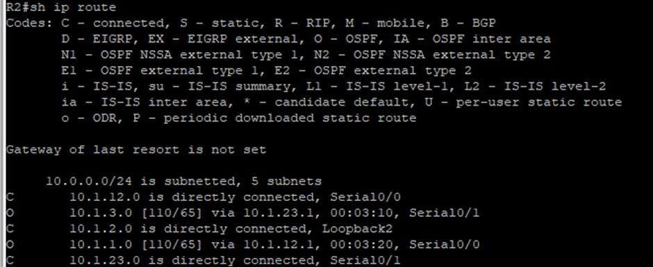
Let's have a look at the R2 routing table.


R2 has directly connected networks and OSPF routes. Noticed R2 has no inter-area routes because R2 is in both areas, acting as ABR.

STUB AREA

Let's make area 2 a stub area. Here we need to configure both R2 and R3. Before doing the configuration, let's have a look at the R2 and R3 routing tables.


The R3 routing table is different. There are inter-area routes, O IA. 

After configuring the STUB area in R3 R3 has a default route pointing towards R2.


A STUB area has not received any external routes. It receives default routes and OSPF inter-area routes.

What advantage of having a default route rather than a more specific route? Router memory and processing are conserved because the router has fewer routes to contend with.

Why do all routers in the OSPF area need to know that the area is STUB? Routers need to know that an area is a stub for consistency. No routes generate LSA type 5. 

TOTALLY STUBBY AREA

We need to configure ABR only.

# area 2 stub no-summary

After configuring the totally stubby area, we can see a single default route from the backbone.
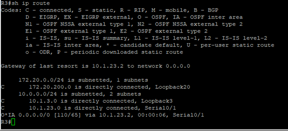

It will remove other routes and have only a default route.

Advantage TOTALLY STUBBY AREA instead of STUB area? Routers in the area only see intra-area routes and a default route. This can save a lot of router memory and processor time. However, if lost any route, it may lose to find the best optimal route.

Why need to configure only ABR other than all routers? ABR is the boundary and ABR passes LSA to others. So, it needs to filter out only LSA type 3 and the default route.

NOT SO STUBBY AREA (NSSA)

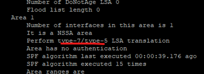
NSSA allows routes to be redistributed from an ASBR into that area with a specific LSA type, which gets converted to a normal external route at the ABR.
TOTALLY NSSA

Let's consider the R3 routing table.


R2(config)

# router ospf 1

# area 1 nssa no-summary

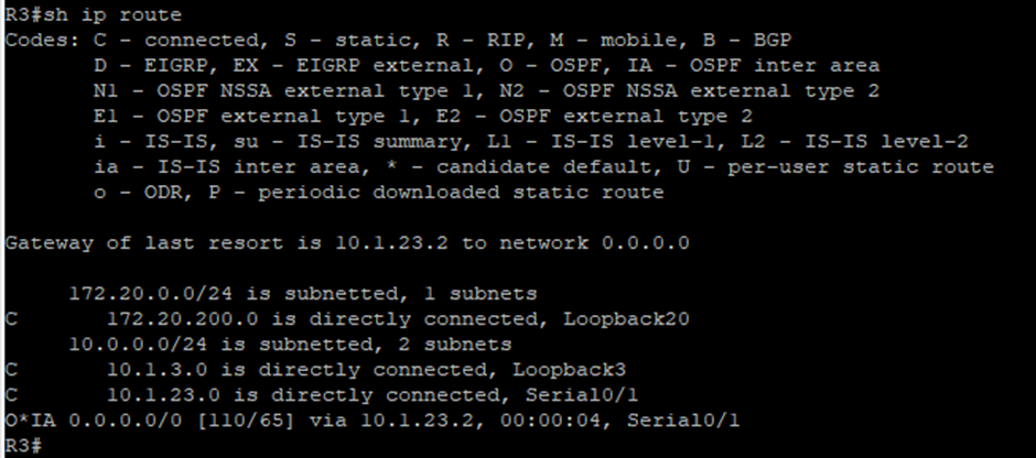
Now R3 will have only one default route, other than directly connected routes.
Where is useful to make NSSA? If want to allow an area to inject external routes into an OSPF domain while still retaining some of the stub characteristics of the area such as not accepting external routes that originated in other areas.

If you have doubts, please don't hesitate to comment below.

ASA Firewall Lab - How INSIDE users access the OUTSIDE web server

Create the below network topology in GNS3. If anyone needs assistance creating the LAB, we're happy to share the Lab sim. 

ASA firewall can ping the web server. User1 can ping the ASA firewall inside the interface.

Now, the user1 wants to reach the web server. When the user1 put a ping to the web server’s IP address, it cannot ping.

User1 cannot ping the web server because user1 is in a private IP address range and the web server belongs to a public IP range. Hence we need to do NAT. Here we are going to use static NAT because the web server has to have one specific IP address.

209.165.20.96/29 is the network of the ISP. We use 209.165.20.99 for the web server. Let’s see how to configure those settings to satisfy the requirement.

STEP1: Check the NAT rules

There hasn’t been any NAT rule configured. Let’s configure a NAT here. Click Add > Add ‘Network Object’ NAT rule.


STEP2: Create a NAT rule


# object network Inside_network

# subnet 10.10.10.0 255.255.255.0

# nat static 209.165.20.99

STEP3: Let’s test the NAT rule. 

Go to user1 and put a ping to the web server IP address.

Cannot ping, but when we check through the ASA # show nat, we can see a count?


STEP4: Check ICMP

Here from the show xlate, we can see NAT was working there. The problem is dropping ICMP. We have to check the service policy rule in the firewall.


STEP5: Troubleshooting ICMP

# policy-map global_policy

# class inspection_default

# inspect icmp

STEP6: Ping test to Web Server

Now we are able to ping the web server from user1.

Let’s see what is happening at the ASA.

NAT is happening and able to ping the web server as well.

Lab completed! If you have any doubts, please don't hesitate to comment below.

Cheers!

Wednesday, October 12, 2022

What is EtherChannel?

Network switches are used to make the network bigger and provide better connectivity throughout the company. When the business is developing there should be involved mission-critical applications and devices to the daily operation. Hence, it needs to have high availability and reliability. In this article, we are going to talk about, how to provide high bandwidth and reliability between switches.

Switch port Aggregation with EtherChannel

The switches can use different types of network cables like Ethernet, Fast Ethernet, and Gigabit. It can provide link speed. Cisco facilitates a technology called EtherChannel. It can enhance the bandwidth of the link by aggregating or bundling parallel links. 

How the link aggregation increases the bandwidth between switches?

Two to eight links can be bundled in the case of Fast Ethernet, Gigabit Ethernet, and 10-Gigabit Ethernet as 10-Gigabit EtherChannel respectively. For an instance, Fast Ethernet can provide a full duplex BW of up to 1600 Mbps (1 Fast Ethernet 100 Mbps, 8 bundles,s and then 16 full-duplex equal to 1600). 

In another word, this is a link to BW expansion as increases the capacity between switches without purchasing additional hardware. Using the same cable, let’s say Fast Ethernet (200 Mbps throughput) can be incrementally expanded up to eight, 1600 Mbps as Fast EtherChannel. If you need more BW, you can use Gigabit Ethernet (2 Gbps through).

Is there a possibility to occur bridging loops and undesirable conditions when bundling?

EtherChannel avoids those conditions by bundling the parallel links to a single, logical link which can act as either an access or trunk link. Here, the end device presented at the end of the link should support EtherChannel for proper operation. 

If you have a 2 Fast Ethernet bundle, you will have 400 Mbps throughput. However, a frame that goes through the Fast EtherChannel doesn’t divide into similar parts and send the frame to another switch or end device. In other words, the load isn’t always distributed equal amount of data through each individual link. This load balancing with discussed later. 

What about the redundancy?

If one link fails, then the traffic is automatically moved to an adjacent link. Failover occurs in less than milliseconds and it is transparent to the end user. If the link is restored, then the traffic will automatically share with active links. 

The initial requirement to bundle the link

EtherChannel supports up to eight links. The same Ethernet media type should use. Some configuration restrictions exist. Hence make sure to use similar configuration links to be bundled. All ports must belong to the same VLAN. If used as a trunk, bundle ports must be in trucking mode. 

Each port has the same speed and duplex setting before being bundled. Bundled ports also must be configured with spanning tree settings.

Distributing traffic in EtherChannel

Traffic will distribute through all the links, but the traffic is not equally balancing through each individual link. Traffic is forwarded through links as per the hashing algorithm. The algorithm can be source/destination IP, or a combination of them, source/destination MAC or TCP/UDP port numbers. The hash algorithm computes and selects a link number to carry each frame. (Many details in the PDF)

EtherChannel Negotiation Protocols

Two protocols are used. Port Aggregation Protocol (PAgP Cisco proprietary) and Link Aggregation Control Protocol (LACP). 

Negotiation

Mode

Negotiation Packets Sent?

Characteristics

PAgP

LACP


On

On

No

All ports channeling

Auto

Passive

Yes

Waits to channel until asked

Desirable

Active

Yes

Actively asks to form a channel


PAgP: Configured in ACTIVE (DESIRABLE) mode, in which the switch actively asks a far-end switch to negotiate an EC, or PASSIVE (AUTO), default mode, in which a switch negotiates EC only if the far end initiates it.

LACP: Ports are selected and become active as per their port priority. 

Friday, August 26, 2022

Doing it Easy: Network Fundamental Summary Notes

OSI Model 

1. Physical Layer: Any media or device that carries 1 & 0s between two nodes. 1 & 0s are bits. Cables/Hub/Repeater.

2. Data Link Layer: Responsible for putting and pulling 1 & 0s  (bits) from the wire to the next source. NIC/MAC. Likewise, it is delivering packets from one NIC to another NIC, hop-to-hop transfer. Frames.

3. Network Layer: Packets delivery from end to end. IP address/Routers. Facilitate communication between networks. 

Packet {DATA + IP + MAC}: 

The computer encapsulates it in an IP header which includes the source/destination IP of the two ends. 

IP header and data are further encapsulated in the MAC address header which includes the source/destination MAC of the current hop. 


Encapsulation and Decapsulation (sending top to bottom and receiving bottom to top)

4. Transport Layer: Responsible for distinguished network streams. The user requested a web address and that web server sends the data to the user. Final point; the user gets that information by 1 and 0s to the user NIC. 

A new user has to identify those 1 & 0s. Layer 4 does this by port numbers. TCP/UDP; 65,536

Layer2 (hop-to-hop) >> Layer3 (end-end) >> Layer4 (service-service)

<---------------------------- delivery -------------------------------------------->

Layer5/6/7: Session/Presentation/ Application Layer;

TCP/IP {Apllication/Transport/Internet/Network interface /Hardware}

Host to Host communication via Switch

Switch (Layer2):  Data Link Layer: Responsible for putting and pulling 1 & 0s  (bits) from the wire to the next source. NIC/MAC. Likewise, it is delivering packets from one NIC to another NIC, hop-to-hop transfer. Frames.

Use source/destination MAC address to make forwarding decisions.

Facilitates communication within networks. 

Learning > Flooding > Forwarding > Filtering 

  • Learning: learn the L2 header and user SRC/DST MAC to make forwarding decisions.
  • Flooding: if the switch receives a frame and it doesn't know about the port, then the switch duplicates the frame and sends it to all ports.
  • Forwarding: switch has a proper MAC address table. Here switch can forward frames via;
    • Store & forward: Store nothing, read the DST MAC and forward the frame. (fastest method). But no error detection. Nowadays switch copied the entire frame into the memory buffer, and checks for errors before forwarding, (slowest). but can prioritize the traffic to move fast.
    • at through
    • fragment free: prior two. inspect only the first 64 bits of the frame. good for error detection while storing the full frame and inspecting it before forwarding the frame. 

Host to Host communication via Switch: Operation

  • Host A wants to send something to host B. L2 header SRC/DST MAC. when the frame is received to switch, it will try to find the host B MAC address. then the switch is duplicated and floods the frame to all its ports except port 1 (filtering). 
  • switch recived the hostA from and then the switch flooded the frame to other ports. Thus host B and C get the frame.
  • hostB accepted the frame and generate a response.
  • when response arrive another MAC table learned, the switch forward the frame to host A.

Broadcast: between the switch flooding behavior, there end result is the same, but there ia a distiction.

Broadcast frame: address to everyone on the LAN done by using same ethernet header except the DST MAC address field is populated with a special address ffff:ffff:ffff. the all F's purpose is for broadcasting. if a switch received a fram with f:, switch cannot find a map. so switch will flood the frame. 

Broadcast is a frame address to everyone on LAN and flooding is an action a switch can take.

What is a Switch? the primary purpose is to facilitate communication within the networks. (hop-to-hop) L2 OSI. SRC/DST MAC, MAC address table. Map MAC --> Switch port. Frame {Data+MAC}

when data comes to a switch, it looks for the DST MAC address and the port. if the destination MAC doesn't know, the switch floods the frame to each port. 

The router? the primary purpose is to facilitate communication between the networks. L3. 

PC A wants to send a packet to PC B. 
PC A sends it to R1 and then R1 to R2 and finally, R2 sends it to PC B. (routing table).

ARP {L2 MAC| L3 IP} ARP uses known IP to discover unknown MAC address. 
PC-A: serverA same network while serverB is in another network. 

PC-A knows serverA IP address. PC-A issues an ARP request for the host's MAC address. ARP supports completing the L2 header. 

If PC-A wants to reach server-B, it sends the request to the nearest router as it is in a separate network, otherwise aka PC-A's default gateway. 


ARP's role is to create a proper L2 header that allows us to find the destination NIC and send the 1 and 0s. 

Host to Host Coummication 
  1. A sends data to B. A knows B's IP.
  2. A creates an L3 header (src/dst IP)
  3. L2 must be created because L2's primary job is to perform the communication within the network.
  4. L2 header (abc=SRC and xyz=DST), here A doesn't know the B MAC address yet.
  5. Hence, A cannot create a proper L2 header to deliver the packet to B's NIC. So A sends the ARP request to find B's MAC. 

6. A asking, if anyone who has 11's IP address, please send me your MAC. Here is my MAC=abc. ARP REQUEST
7. ARP request sends as a broadcast because A doesn't know about host B yet.
8. ARP response: Unicast; directly address to host A). 

Router Function is to facilitate communication between networks. ARP table bridge between L2 -> L3. 
  1. HostA packet --> R1 (a packet deliver to the R1 default gateway)
  2. hostA creates L3 header {SRC|DST hostA IP address}
  3. L3 header is not enough to deliver the packet to hostB.
  4. hostA encapsulate L3 header in L2 header which includes {SRC MAC host A, DST MAC R1)
  5. now R1 has the packet, now DST will be host B. this destination exist on R1 routing table. 
  6. R1 has L3 header and create L2 header to find the DST (host B MAC)
    1. R1 host A and DST host B IP adress.
    2. SRC: R1 int MAC = L3 header
    3. DST: host B MAC = L2 header
  7. L3 header is not changed which created by hostA. 
If you have any questions, please don't hesitate to comment below. Follow us for the latest news, new articles, doing-it-easy tutorials, labs, software, free exam vouchers, dumps, and many more. Cheers! 

Tuesday, March 22, 2022

Policy Base Routing - Router unwanted traffic via low bandwidth link

Let's say UserA and UserB are connected to the R4 router.

IT team noticed UserA is playing games on the Internet. IT team wants to traffic UserA packets via a slow bandwidth link.

UserA -> R4 -> R3 -> R2 -> R1 (which is lwo bandwidth)

UserB -> R4 -> R3 -> R1

HERE POLICY BASE ROUTING

R3 configuration

# ip access-list standard PBR-ACL

# permit 192.168.4.128 0.0.0.127 ((which is USERB traffic))

# exit

# route-map R3toR1 permit

# match ip address PBR-ACL

# set ip next-hop 172.16.13.1 (the interface which is facing to R3 from R1)

# exit

# int s0/0

# ip policy route-map R3toR1


See... now the 129 UserB traffic going as per the proposed design. 

R3# debug ip policy 1


SUMMARY AND ERROR FIXING ACL


1. All the routers are configured and apply the EIGRP as the routing protocol.

a) Now its able to ping all IP addresses in the topology.

b) Ex: R1 can ping to R4 and vice versa.


2. But see the connection between the routers are having different size of bandwidth. Ex: From R1 to R2 = 128 BW. So when we traceroute from R4 loopback interface with its 4.1 or 4.129, the traffic path would be the same as it is getting higher bandwidth path as per the cost of EIGRP.

a) As a summary, it takes the path as from 4.1 network
R4 -> R3 -> R2 -> R1 -> 192 network.

b) Let’s say we want to forward 4.129 traffic via low cost bandwidth which is 64 as from R4 -> R3 -> R1.

c) Here we have to use the amazing feature Path Control Policy Base Routing.


3. Let’s configure the R3 router.


# ip access-list standard PBR-ACL

# permit 192.168.4.128 0.0.0.127

We are going to permit the 4.128 network via PBR-ACL


Creating a route map to apply in.

# route-map R3toR1 permit

# match ip address PBR-ACL

# set ip next-hop 172.16.13.1

Apply this route map to the interface facing to R4 router.

# int s0/0

# ip policy route-map R3toR1


Now all done? Not yet, we allow only 4.128 network via ACL. Last line implicit deny rule apply by default and it will not allow the 4.1 traffic and deny 4.1 traffic.


So we need to create another ACL to allow 4. network traffic on R3

# access-list 1 permit 192.168.4.0 0.0.0.255

# exit


Let’s see the router now.


Now let’s test this.

# debug ip policy 1


See, now the 4.129 traffic go via R3 -> R1 instead of going towards to R2.


Tuesday, March 8, 2022

Cisco FMC and FTD Firmware Upgrade - New Interface 2022


FMC and FTD Firmware Upgrade

1. Check the TAC support.

2. Send SOC for firmware recommendation.

3. Propose patching date to the customer.

4. Open a Cisco TAC case.

5. Send email to customer confirming the date.

Procedure (1) FMC

1. Take back up from FMC and FTD on both devices.

2. Download the back to a shared location.

3. Send an email to the customer before the outage.

4. Click on Systems > Update to install the firmware on FMC.

5. Run readiness check for errors. Readiness check: this will take 10 minutes. when starting it, nothing will progress, but after that, it starts to show the progress bar.

6. It will pass the check and then you have to press the install button. When clicking on the install button, it will directed to update/System page. Then you can see the task tab to see the progress.

7. This will take 60-90 minutes to reboot the FMC. Meantime, the web GUI disconnected. We can ping the IP. But cannot log in using our domain credentials. I used an admin account. (The login page looks traditional). When you log in, you can see the progress.

8. There isn’t any network interruption. Installation (may take 60-90 minutes)

9. When rebooting the FMC, you cannot access it via your credentials. You have to log in via an admin account. Then you can see the progress. (Here, at 9% it took 30 minutes, and then 22% took another 30 minutes).

10. When rebooting the FMC, a msg popped up on the WEB screen saying the system is rebooting.

11. This time you cannot ping, So put a continuous ping and verify the FMC connectivity.

12. Once ping success, after a couple of minutes you can access the FMC via WEB with your credentials. When the page is refreshed, it will take a little time to load the page. Then you can login via domain credentials.

13. Verify the upgrades firmware.

14. Send an email to the client.

Procedure (2) FTD devices.

1. System Update and install.

2. It will install the firmware for the secondary device as it is.

3. This will take 30 minutes to upgrade the secondary.

4. While installing the process you can see, retry, and remove maintenance messages. Don’t panic here. It takes time and finishes the installation for secondary. Meantime you can see it has been upgraded to the new version.

5. Rebooting the FTD.

6. Then this happens to the primary device.

7. When rebooting it goes to secondary due to HA.

8. After completing both, you can see the upgraded version on FTD in the device tab.

9. Then you must deploy the policies if it's available to do so.

10. Here, you can see the warning and error before pressing the deploy button.

11. All completed.

12. Send an email to the client and close the change.

 #FMC #FTD #7.0.1


Wednesday, February 16, 2022

Testing and proving the difference between Extended ACL vs. NAMED ACL

  Extended ACL vs. Named ACL


Case1:

We need the BLOCK the traffic from PC2 to PC1

Allow others.


Use a Extended ACL

# access-list 100 deny ip host 192.168.2.100 host 192.168.1.100

# int f0/1 (R2 interface to SW2)

# ip access-group 100 in

Here ALL GOOD as we cannot ping PC1 from PC2, but can ping other devices.

But when we try R3, it also cannot ping

PING from PC2 to PC4 also fails.

That’s means implicit deny rule there.


Adding an ACL to ACL 100.

R2(config)#access-list 100 permit ip any any


Now::

When ping from PC2 --> PC1 Deny due to RULE 10 sequence

When ping from PC2 --> other allow (able to PING) it goes via 20 rule. Permit any any.

Now the manager wants to disable ping from PC2 --> R3

Let’s add a deny rule to access-list 100

R2(config)#access-list 100 deny ip host 192.168.2.100 host 192.168.1.254


But this does not work and why?

Ping from PC2 --> PC1 fail (due to denying rule 10)

We think after adding the deny rule to the R3 network will deny the ping from PC2 to R3.

But not, because 20 rule ANY ANY satisfied the ACL as it permit any network to any destination.

Even 30 rule is there, after satisfying the ping from rule 20, it will not check the rule 30 sequence.


However, don’t remove the any any rule, it will remove the all ACL 100.

Let's try to add ACL 101 to deny R3


NOW !!! we cannot ping the device due to deny rule and after that implicit deny rule.


We add ANY ANY rule to 101 ACL


Now,

Ping from PC2 to R3 DENY

Ping from PC2 to other devices ok means 100 ACL 10 sequence is not working.

That rule skips because there is 101 ANY ANY rule.


So, now the problem is, when ACL is there, how to block another IP.

When we implement a new ACL it will skip other rules.

If we put the RULE into the same ACL (100), a sequence number set and rules go to below and the top rules are not working because of ANY ANY rule there.


The BEST solution here is to USE NAMED-ACL. it can set the SEQUENCE.

So if any rule is satisfied it will APPLY the RULE and don’t go further as checking the next RULE sequence.

Let’s implement this.


DENY PING from PC2 --> PC1

ALLOW PING from PC2 --> Other devices

BLOCK PING from PC2 --> R3


R2(config)#ip access-list extended BLOCK-PC1

R2(config-ext-nacl)#deny ip host 192.168.2.100 host 192.168.1.100

R2(config-ext-nacl)#permit ip any any


10=deny ping to PC1

20=allow ping to other devices.


NOW apply a rule to block R3


Here DENY 30 rule is not working, ping R3, it will allow by 2 rules and be satisfied.

So we need to get the RULE sequence between 10-20 to deny the R3

R2(config)#ip access-list extended BLOCK-PC1

R2(config-ext-nacl)#no 30 deny ip host 192.168.2.100 host 192.168.1.254

R2(config-ext-nacl)#15 deny ip host 192.168.2.100 host 192.168.1.254


DONE DEAL….. LAB DONE!!!!!

PC2 cannot ping PC1 and R3.

But can ping 4 network.


Let’s go further.

Let’s block the 4 network by new NAMED-ACL rule


OH NO! Block all devices. Because after the new NAMED ACL, it takes the sequence.

SO NEW rule has to be checked 1st.

To deny all traffic


What happens, if we apply new ACL 200 to allow PC1


PC1 is okay because we permit it.


But as that implicit deny rule will block all devices.


TESTING!!!!!! RESULT!!!!!

NAMED ACL is better….

Because;

Ping deny from PC2 to PC1

Put allow the rule to allow other devices.

ALL OKAY.

Meanwhile, the manager asked to blow R3.

Apply a rule to block R3

IT WILL NOT WORK.

WHY? Because 2nd sequence is ANY ANY RULE.. it will satisfy and not check the next sequence rule as the new rule to block R3.


Solution:

Check the show access-list

APPLY NAMED ACL (already created one)

Change the SEQUENCE BETWEEN THE RULES.


DONE!!!! CHEERS!!!! ACL DONE!!!!
